If you look at the schematics, there are several type of +12 v sources. One is always on, directly from the battery. Another is only on when the key is in the “On” position, another is only on when the key is in the “Start” position.
The one I’m interested in is the one that is on only when the engine is running. The crankshaft has to be rotating to turn on this signal. It is used to control things like the fuel pump, which you only want to run when the engine is running.
On my 1970’s Ford truck, with points, distributor, and carb, they did it by running a signal from the alternator, for powering the automatic choke. It only has voltage when the alternator is turning; hence only when the engine is running.
On a 1970’s VW Rabbit, with points, distributor, and fuel injection, a signal from the ignition points was used to trigger a relay on, which in turnn was used to run the fuel pump; again, it only turned on the relay when the engine was rotating.
On a 1990’s Toyota, with no points, but w/a mechanical distributor, and fuel injection, I think they did it on that car with a magnetic sensor where the points used to be. It sensed when the distributor shaft was turning.
So I’m curious, what with cars having neither points or a mechanical distributor, how do they do it these days?
The Crankshaft Position Sensor is one of the primary inputs to the engine management computer. As long as the computer recieves a signal from this sensor, the computer knows the engine is rotating so it continues to operate all the other engine management controls.
How does this sensor know the crankshaft is turning? Do they put a magnet on the crankshaft and a hall-effect sensor to sense as it passes by? I.e. is it located right on the crankshaft, the crankshaft pulley, the flywheel maybe? I mean for newer cars. Just curious.
The crank sensor is a hall effect sensor. A magnet that reads a missing section of a rotating component.
A crank sensor can be found at the front of the engine behind the crankshaft pulley, screwed into the side of the engine block, or mounted back at the transmission.
I think you’re clearly over-thinking this, or just have a misconception.
The ignition switch controls each of these three functions. In the typical automobile, the ignition switch has one position for ‘Accessories On’, ‘Ignition On, including accessories’, and ‘Start w/ Ignition On, but no Accessories On’.
On the 1970’s Ford Truck, it had a mechanical fuel pump driven by an eccentric on the camshaft that would only pump when the engine was turning, either running or by the starter. The ignition was powered only when the switch was on ‘Ignition On, including accessories’ through a ballast resistor to cut the voltage to the coil to 6 volts, and ‘Start w/ Ignition On, but no Accessories On’ that by-passed the ballast resistor to send 12 volts to the coil for extra spark. The choke line is attached to the 12 volt ‘Ignition On’ circuit, not the alternator.
I cannot tell you how the 70’s V-Dub worked, but that may sound plausible. The Germans are a strange bunch that tend to over-engineer a lot.
But, the 1990’ Toyotas, of which I still have a couple, have the fuel pump controlled by the ECU. Since the ECU controls the ignition, ignition timing, and fuel injectors through various sensors, it knows when the engine is running and turns on the fuel pump relay when it is running. On start-up, it typically runs the pump for 2 seconds to prime the pressure in order to start the car. Then turns the pump on full once the engine is running.
All modern cars also have these functions run by the ECU. It knows full well when to turn on the fuel pump, also by various engine sensors. Each engine seems to have it’s own priorities when it comes to sensors, but the most important one in many is the crank angle sensor, followed closely by the camshaft position sensor. Others put the camshaft position sensor first.
The Camshaft Position sensor is for fuel injection timing only. You can have a Camshaft Position sensor failure but the engine will still run because the computer goes to a default value for injection timing. Tho the engine will run a little richer and not so well. But if Crankshaft Position sensor fails, the engine shuts down right now.
The four primary inputs into a modern vehicle computer are, the Crankshaft Position sensor, the Throttle Position sensor, the MAF/MAP sensor, and the Coolant Temperature sensor.
The reason I said ‘most’ is because the 1992 Toyota Supra Turbo doesn’t have a crank angle sensor, only the camshaft position sensor. I know, I have one. It has port EFI and coil packs. Also, the 1998 Nissan Quest van also uses the camshaft position sensor for these tasks. The crank angle sensor is only for double-checking the camshaft position sensor according to the Nissan Shop Manual. It will run fine if the crank angle sensor is disconnected, but a CEL will light. Not all cars are created equal.
Oooooh BUSTED…you mean to tell me that have one of my FAVORITE Sports cars? One of the MIGHTIEST Toyotas ever made? Those are getting rare to find and more and more expensive to buy. I KNEW that was going to be a classic the first time I laid eyes on it… Mmmmm S-U-P-R-A… What a Beautiful engine in that car!..so nice…and they can be SO Violently EVIL as well…
Tester is right of course so I will put the answer in a different form. Modern vehicles have a brain (ECU) which use the sensor inputs to control the engine. The ECU is a computer so engine management is a fairly simple task for such a complex device. The ECU knows exactly when the engine starts and stops.
Busted Knuckled indicates 1970’s Ford V8 has auto-choke connected to +12 ignition “on”. This is incorrect, at least for my 1970’s Ford truck V8 302 w/Autolite 2150 carb and electric choke.
The schematics clearly show the power to the electric choke comes directly from an alternator winding. Not the +12 ignition “on” line. Also, note the comments in this thread that the auto-choke voltage is normally 8 v, not +12.
It may be the case that the alternator winding which sources the +8v to the auto-choke is powered up w/the engine not running. I didn’t ever test that to see. I expect it isn’t powered though with the engine not running. It appears like the car designers only wanted the auto-choke to be powered up when the engine is running. Maybe a safety issue. Anybody know?
Thanks for the other comments on how newer cars know if the engine is running. It seems there are as many ways as there are cars!
My query is just basic curiousity – born out of some recent work I’ve done on a 1970’s Ford auto-choke. Just curious is all.
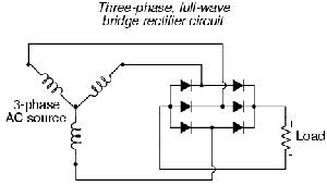
The 8V line from the alternator is the center of the three “Y” connected stator coils.
It puts out AC voltage, only when the alternator is spinning and the field winding is energized.
This line traditionally controls the battery/charge warning light on the dash.
The choke heater doesn’t care that its getting AC power vs DC.
I find this whole thread confusing. The ECU doesn’t check anything at all to determine if the car is running. The way it works is that if the key is in a specfic position, specific circuits are “enabled” (connected). If those circuits are “enabled” and the ECU doesn’t get the expected signals from the sensors that it uses to determine engine demand and crank position, or if the signals are abnormal, it simply won’t eun, will run poorly (by processing the bogus signals and sending bad commands), or will run by trip a Check Engine Light. These “enabled” ciruits are generally through relay contacts, which open when the key is turned to the “off” position and allow those circuits to deenergize.
Re: the fuel pump question, the fuel pump circuit is energized whenever the key is in the “start” or “on” positions, assuming that the inertial sensor (designed to shut the fuel pump off in an accident) has not been tripped. Whether it runs or not does not depend upon the ECU.
Circuits that are always “enabled” would include things like the security system, the acessories like the dome lights and power outlet, the emergency flashers, and (in older cars) the headlight circuit. These circuits are kept energized at all times to enable their use no matter what position the key is in.
In short, I think you’re looking at this backwards. All the circuits needed to operate the vehicle are enabled whenever the key is in the “on” position. And they’re all powered by the battery. The battery is kept charged by the alternator, and of the engine isn’t operating to turn the alternator all the circuits remain enabled and the battery runs down until it can no longer keep the relay coils energized. The ECU doesn’t “know” whether the engine is running or not.
Bosch EFI systems have used the MAF to signal the ECU to turn on the fuel pump and injectors. I have jumped that circuit on several European cars to keep them running while waiting for a replacement part.
The pump as well as the injectors? I could see where the lack of a MAF signal would prevent the injectors from firing, and once the fuel system is pressurized the pump would shut off, but I’m surprized the ECU actually turns the pump on directly.
I believe you, 'cause I know you know your stuff, it just surprizes me.
Thanks Circuitsmith. Your post was helpful and informative.
Also, you have shown me that I don’t understand how an alternator works. I always thought the stator was energized by the battery, and the rotor windings (crossing the fixed magnetic field lines of the stator when the rotor is turning) were the source of the electrical power. Apparently – from what you say – it is the reverse. The rotor windings are energized by the battery (and when it rotates, it forms a moving magnetic field), and the stator windings convert this changing magnetic field which cross the stator windings into a current to charge the battery and supply current to the vehicle while it is running.
Actually, George, it could work either way in principle.
However there’s two good reasons it is done the way it is.
First, if the 3 phase windings were on the rotor it would need at least 3 slip rings and brushes.
Second, the field winding pulls less than 5 amps, so the slip rings and brushes are under a light load.
If the output windings were on the rotor the brushes would have to handle 30 amps or more each.