2 Volts on Automatic Shut Down Relay Circuit - 2000 Chrysler Voyager 2.4L

I have a 2000 Chrysler Voyager 2.4L van. When I try and start the vehicle it will crank but will not start. I have checked all 4 spark plug wires and I don’t get any spark on them. When I probe the input to the ignition coil pack with the key in the on position I get around 2 volts. When I try and start the car the voltage will fluctuate but doesn’t get above 7 volts. I have unplugged the Automatic Shutdown relay and still get the 2 volts. If I unplug the fuse that lets power to both the Fuel pump relay and also the entire PCM the 2 volts goes away, but that is sort of a shotgun. My questions are:

Should I see 2 volts on this circuit when the key in the on position?
If not, how do I go about finding where the excess voltage is coming from?

Thanks!

Bear with me, please.

I’m not sure what auto shut down relay stands for.

But looking at that wiring diagram, it seems to be that the auto shutdown relay should be energized with the ignition on.
So you should have B+ at the ignition coil pack with ignition on. Since you have 2V, perhaps the relay is defective.

If the oxygen sensors and generator are also only getting 2V, that should narrow it down.

Where does the ignition coil pack get its ground?

But, like I said, I’m not familiar with that relay. I’m only speculating, based on the wiring diagram.

By the way, is that relay available separately, or is it integrated into the power distribution center (fuse box, I presume)?

In my opinion, removing that 20A fuse 3 is actually creating a problem. It appears that removing it will GUARANTEE a no start. With that fuse removed, even a good relay would not get energized.

Insert a jumper wire from the holes for pins 30 to 87. That will complete the circuit for the relay and the engine should start if the relay is the problem.

AUTOMATIC SHUTDOWN (ASD) SENSE - PCM INPUT
It is an input to the Powertrain Control Module from the rely in the Power Distribution Center, refer to the cover for relay location.

The ASD sense circuit informs the PCM when the ASD relay energizes. A 12 volt signal at this input indicates to the PCM that the ASD has been activated. This input is used only to sense that the ASD relay is energized.

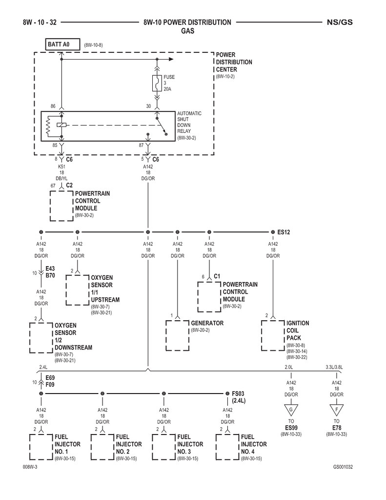
When energized, the ASD relay supplies battery voltage to the fuel injectors, ignition coils and the heating element in each oxygen sensor. If the PCM does not receive 12 volts from this input after grounding the ASD relay, it sets a Diagnostic Trouble Code (DTC) .

When energized, the ASD relay provides power to operate the injectors, ignition coil, generator field, O2 sensor heaters (both upstream and downstream), and also provides a sense circuit to the PCM for diagnostic purposes. The PCM energizes the ASD any time there is a Crankshaft Position sensor signal that exceeds a predetermined value. The ASD relay can also be energized after the engine has been turned off to perform an O2 sensor heater test, if vehicle is equipped with OBD II diagnostics.

With SBEC III, the ASD relay’s electromagnet is fed battery voltage, not ignition voltage. The PCM still provides the ground. As mentioned earlier, the PCM energizes the ASD relay during an O2 sensor heater test. This test is performed only after the engine has been shut OFF. The PCM still operates internally to perform several checks, including monitoring the O2 sensor heaters. This and other DTC tests are explained in detail in the On-Board Diagnostic Student Reference Book.

AUTOMATIC SHUTDOWN RELAY - PCM OUTPUT
Fig. 1 Powertrain Control Module (PCM)

The ASD relay and fuel pump relay are located in the Power Distribution Center (PDC) near the Air Cleaner. The inside top of the PDC cover has a label showing relay and fuse location. They are ISO relays.

The PCM operates the Automatic Shut Down (ASD) relay and fuel pump relay through one ground path. The PCM operates them by switching the ground path for the relays ON and OFF.

The ASD relay connects battery voltage to the fuel injectors and ignition coil. The fuel pump relay connects battery voltage to the fuel pump.

The PCM turns the ground path off when the ignition switch is in the OFF position, unless the O2 Heater Monitor test is being run. When the ignition switch is in the ON or CRANK position, the PCM monitors the Crankshaft Position Sensor and Camshaft Position Sensor signals to determine engine speed.

If the PCM does not receive a Crankshaft Position Sensor signal and Camshaft Position Sensor signal when the ignition switch is in the RUN position, it de-energizes both relays. When the relays are de-energized, battery voltage is not supplied to the fuel injectors, ignition coil and fuel pump.

The low voltages you are seeing are not what you would normally see if the problem wasn’t happening but they are what you might expect to see due to the way the circuits are designed. Here is what the drawing is showing you starting at the top. The fuse and relay coil in the PDC panel under the hood are connected to the battery which has 12 volt power. Any wires tied to that line will have 12 volt power on it so fuse 3 connects that power to the relay contacts and on to all those devices shown below the PDC when the relay is turned ON. The other side of the relay coil goes to the PCM module and it turns on the relay by making an internal ground connection (power is tied to the other side of the coil) inside the module. That will close the relay contacts pins 30 and 87 so the arrowed line will now be on pin 87 instead of off to the right making no connection. The drawing shows the relay in an open condition as it would be when the ignition is OFF or the PCM forces the relay to turn OFF (the relay coil connection through the PCM to ground will go away). The ASDR relay is a safety device in case the PCM detects an unsafe condition for the engine to be running.

Use your meter to verify fuse 3 has power on both sides of it. Use the small slits on top of each side of the fuse. If that is ok then make sure power is getting to the relay on pin 30. There could be a bad connection between those points or others after that. Your meter will show you what the truth is.

By checking the voltage on the wire connection running between the relay coil and the PCM you can determine if the relay is supposed to be on or off. When you have near zero volts on that lead the relay should be ON and if there is near battery voltage at that point the relay will be OFF.

Since the PCM controls the relay you may find there is nothing wrong with the relay circuit and something else is causing the PCM to force the relay to the shut down mode.