Engine idling, no load
Actually with core charge and shipping this acdelco reman still comes out to the same base price as the valucraft one. More Information for ACDELCO 3341468A (rockauto.com) I feel like this would be better bet.
Engine idling, no load
Actually with core charge and shipping this acdelco reman still comes out to the same base price as the valucraft one. More Information for ACDELCO 3341468A (rockauto.com) I feel like this would be better bet.
Your replacement choice seems like a good one to me too.
It’s hard to imagine you could be measuring 25 volts AC at the battery when the alternator is connected to the battery, at idle. The battery’s capacitance usually severely tampers down any AC oscillations coming from the alternator. But I guess such a thing is possible. What was the DC voltage measurement at idle? The big AC measurement sort of makes me wonder if somehow the alternator isn’t making a good connection to the battery.
How much AC voltage does a car alternator put out?
An alternator is so named because it produces alternating electrical current. This energy can be converted from one voltage to another using a transformer. Thus, the 12-volt AC output from an alternator can be transformed into 120 volt-AC current.
Tester
Today it couldn’t have been anymore than 12.2 volts.
The voltage drop tests I did read just a few milivolts. This would rule out a bad connection?
You can charge your battery with a battery charger and continue to drive your vehicle for short trips.
With the ignition on but the engine not running you can set your multimeter to the milivolt scale and measure between the battery negative terminal and where that wire connects to the chassis, if you can find the other end. This gives you a relative idea of how fast your battery is discharging. Then turn the headlights on and measure it again. Always put the meter probes in the exact same spots. The Voltage measured on the meter will be higher now. That’s how much faster your battery will discharge with the lights on or whatever other load you turned on.
Your alternator has failed. It could be the rectifier, or the regulator, or even the slip rings that provide Voltage to the field winding. Or possibly the ON wire that tells the alternator to turn on that connects to the electrical connector on the back of the alternator has stopped working, or the fuse in the vehicle that powers that circuit is blown, but I don’t think that’s the case because if so the alternator fault light wouldn’t be working. Those wires on the alternator usually consist of an ON wire, a fault light wire, and a PWM input that lets the ECU adjust the charging rate. If you want to you can take the alternator apart and replace the individual components, if parts are available.
It means that there is hardly any current coming out of the alternator. You’re using the wire as a current sense when you measure it like that. It also shows if the fusibile link wire opened up electically, which would show a large Voltage difference.
I didn’t know about that trick! What you’re doing is measuring if the alternator field current active right? There should be a difference in screw driver pull between ignition off and on.
Interference from the ignition interferes with many digital multimeters. Touch the test leads together to test for interference. It won’t show 0 like it should if there is interference.
Around 100 Volts AC at 3000 RPM engine speed with full field current and no load. Automotive alternators are very inefficient. In the real world it won’t put out 100 VAC because either the battery will be there to bring it down to about 16 VAC or the TVS diodes in the rectifier will clamp the Voltage below 32 VAC and the regulator will immediately turn off the field to bring the Voltage down.
Correct. The test was to see if there was a large Voltage drop, something over 1 Volt that would indicate a broken or loose wire.
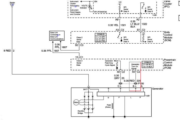
From the posted diagram above, I’d have expected the red wire (ID’d above/left as 8 Red 2) to measure battery voltage (i.e. 12.6 volts) rather than 4.99 volts. Hard to say for certain without seeing the entire battery/charging system/starter wiring schematic.
Ok, that one looks like a logic-level output from the alternator indicating the alternator is either on or off. Logic levels are often either 4-5 volts or 0-0.2 volts, so that’s probably correct. Usually computer circuit designers indicate whether a logic signal is either an input or an output with arrows, but I don’t think those arrows on the A,B,C points have any meaning. I’ve notice this on other car schematics too, for some reason the conventional arrow convention doesn’t apply. So it could be a signal from the PCM to turn on the alternator too.
BTW, the magnetization is caused by current flowing in the alternator’s “field” coil. Shown in the diagram above. The diagram unfortunately isn’t specific what causes that to occur.
I thought that would have been the 5v supplied through it during key on since that was the condition required for the screwdriver/pulley test mentioned above.
The “Generator field duty cycle signal” turns on the field, the engine must be running for the computer to switch on the field control.
I was wondering about this. It appears to be true that newer vehicles won’t energize the field in the alternator unless the engine is running. In the past the ON wire was controlled directly by the ignition key.
The alternator in my 1996 Dodge is controlled by the PCM. Chrysler has used computers to control charging system voltage based on need since 1985.